Tilt-shift, a DIY guide - part 3, Building a DIY tilt-shift lens
Posted on Sat 03 July 2010
Building a custom DIY tilt-shift lens is an easy introduction to the world of homemade lens hacking and building. Why build your own? The first big factor is cost - DIY tilt-shift lenses typically cost around US$20-50, whereas professionally built options start out at ~US$1300 (notes on more affordable commercial options are in Appendix B). The designs below involve a minimal amount of hacking, and should be relatively simple starter projects for the amateur lens enthusiast. The second factor is simply the pleasure that is derived from building and shooting with something that you have made yourself.
Choosing a lens

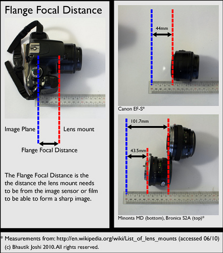
Modern SLR lenses are complex pieces of optical engineering. They are often built from several lenses which correct for distortion and various optical artifacts. The lenses are designed so that they must be at a precise distance from the sensor or film to form a sharp image. As shown in above, this distance is commonly known as the Flange Focal Distance, which is measured as the distance between the lens mount and the sensor or film in the camera. Different lens and body combinations have different distances; an excellent table of lens system parameters (which includes the flange focal distance) can be found on wikipedia here.

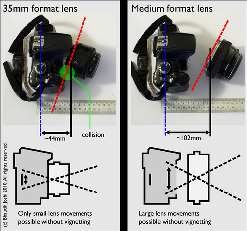
As shown in the left box in the figure above, it's entirely possible to use an unmodified standard lens for DIY tilt-shift work. This is often performed by simply holding the lens in front of the camera and tilting the lens, and is commonly referred to as freelensing. On it's own it can produce good results, as shown in the examples below. However, the edge of the lens will bump into the lip of the lens mount, limiting tilt movements. This can be minimised by choosing a lens with a smaller throat diameter. Ideally you'd like a lens with a narrower diameter than the mount of the camera, so it can sink into the body a little if needed to allow for a greater range of movements. Sinking anything near the mouth of the camera body requires a great deal of care, so again be careful not to collide the lens with the camera mirror. Moreover, leaving a gap open to the air between the lens and the camera body will easily allow contaminants and dust on to the film or sensor, as well as introducing significant light leaks into the image.


This approach has some immediate drawbacks. If you are using a full-size sensor or film, any lens movements will cause serious vignetting (i.e. when the image cast by the lens moves off the sensor). Even if you are using a smaller sensor (such as an APS-C) then the lens movements are still somewhat limited before vignetting occurs.
The fix for this is to remove the back of the lens so that a greater range of lens movements are possible at the flange focal distance (see Modifying a Lens, below), or to use a lens that has a larger flange focal distance (see Plungercam 2, below). The latter approach can be achieved for 35mm cameras by using a medium format lens (the right-hand box of the above figure), which typically have a flange focal distance at least double that of standard 35mm lenses. Better still, the lenses are designed to create an image for a film/sensor that is much larger than 35mm, so a much greater range of lens movements are possible without vignetting. This is holds equally true when you are coupling lenses for a larger sensor/film with a smaller camera body - for example, using medium-format lenses with a standard-format camera body, or, more interestingly, standard 35mm with a micro 4/3 camera body (example here).
| Body type | Lens type | Works? | Notes |
|---|---|---|---|
| Micro 4/3 | Micro-4/3 | Maybe |
This might work, but the lens would need modification |
| Micro 4/3 | 35mm | Yes |
This seems like a good combination |
| Micro 4/3 | Medium format | Yes |
This seems like a great combination - a huge range of lens movements would be possible |
| 35mm SLR (crop sensor) | Micro-4/3 | No |
The micro 4/3 flange focal distance tends to be way too short |
| 35mm SLR (crop sensor) | 35mm | Maybe |
This might work - you'd need to verify this by experimenting via freelensing |
| 35mm SLR (crop sensor) | Medium format | Yes |
This seems like an excellent combination |
| 35mm SLR (full frame) | Micro-4/3 | No |
The micro 4/3 flange focal distance tends to be way too short |
| 35mm SLR (full frame) | 35mm | Maybe |
This might work - you'd need to verify this by experimenting via freelensing |
| 35mm SLR (full frame) | Medium format | Yes |
This seems like a good combination |
| Medium format | Micro-4/3 | No |
The micro 4/3 flange focal distance is way too short for this |
| Medium format | 35mm | No |
The 35mm flange focal distance is too short for this |
| Medium format | Medium format | Maybe |
This might work - you'd need to verify this by experimenting via freelensing |
Compatibility chart for DIY tilt-shift lenses. Note that this is only a rough guide, and compatibility can only be properly verified by experimenting |
The compatibility chart above outlines the rough combinations of lens and camera bodies for DIY tilt-shift lenses. It's by no means completely accurate, and based largely on my own small set of experiments and observations. Any lens you choose to use for tilt-shift work can be easily tested by freelensing - leave the body cap off the camera, and slowly move the lens towards the camera body to see if a sharp image is formed. If you can form an image without the lens colliding with any camera internals, then the lens is probably suitable for DIY lens building.
How to initially choose a lens for suitability
I'd recommend roughly evaluating if a lens is going to be suitable for building into a DIY tilt-shift lens. This is easily done by first setting up your camera body on a tripod, in an area that has objects both near and far away. Set your lens to infinity focus, take the body cap off the camera and place the back of the lens next to the camera body (being careful not to bump the mirror!). Looking through the viewfinder, move the lens forward and see if you can form a sharp image of near or far objects. If you can't form a sharp image, then the lens is probably unsuitable. If you can, then it may be worth slightly tilting and shifting the lens when it is in a sharp focus position to determine what kinds of movements this lens might permit. From here you can also estimate what movements cause vignetting.
Retrofocal lenses
Many wide-angle SLR lenses use the Angenieux retrofocus lens design, which places a large negative lens element at the front of the lens allowing for a greater back focal distance than would otherwise be possible. This larger distance allows the rear lens element to be a good distance from the film/sensor, and in SLR cameras allows for room for a mirror. Some commercial tilt-shift lenses also use the retrofocal design, with an extra long back focal distance and larger imaging circle, which is exactly what we'd like to emulate by choosing coupling a larger-format lens type with a smaller-format camera body. For example, compare the rear-element to rear-flange distance on a normal 24mm lens with a 24mm tilt-shift lens.
Effect of lens choice on tilt angles

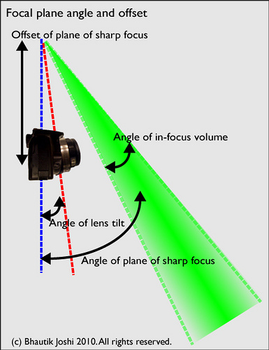
Different focal length lenses will respond differently to lens tilt (see tilt analysis, above). Generally speaking: As lens focal length increases: The angle of the plane of sharp focus decreases (for any given lens tilt angle) The offset of the plane of sharp focus increases (this really only is significant for objects close to the camera)
As the f-stop increases: * The angle of the in-focus volume increases
This means that short focal length lenses are more sensitive to tilt, and faster lenses produce a shallower depth-of-field volume. Some of these relationships are not obvious, and a more detailed look into these relationships can be found in appendix A.
Modifying a lens to fit

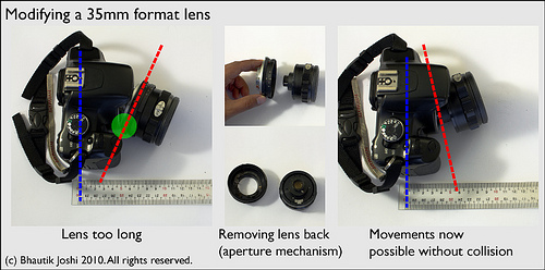
35mm lenses can be adapted to tilt-shift work by making them more mechanically suitable. This kind of modification is quite destructive and requires disassembly of an existing lens to make it work. I'd highly recommend using an old and inexpensive lens for this. As shown in the diagram above, lenses matched to the same format (here, a 35mm format lens with a 35mm SLR) will collide with the camera body when tilted, as indicated by the region in green. To solve this problem, many older lenses can be disassembled to remove their mounts and aperture setting mechanism. In this case, I've taken the back mechanism off a 28mm Minolta Rokkor. Once the lens back is removed, the range of movements is much greater.
To disassemble the aperture mechanism you will need to identify where this mechanism is and remove it. Most lenses that I have come across have the aperture mechanism held on by screws, and only minimal force is required. Some, however, will require forceful disassembly, and careful use of a hacksaw may be needed to achieve this.
Zoom lenses can be adapted for use as tilt-shift lenses, but there are a few things to note. In certain zoom configurations, these lenses tend to have a large space between the back lens element and the flange. By keeping this distance and removing the rear lens housing, it is possible to allow for large lens movements as the back lens element will not collide with the camera body. However, the back mechanism for zoom lenses tend to be much more complex than for prime lenses, so extra care must be taken when disassembling the lens back.